Monday, November 4, 2013

Switching out LED strips

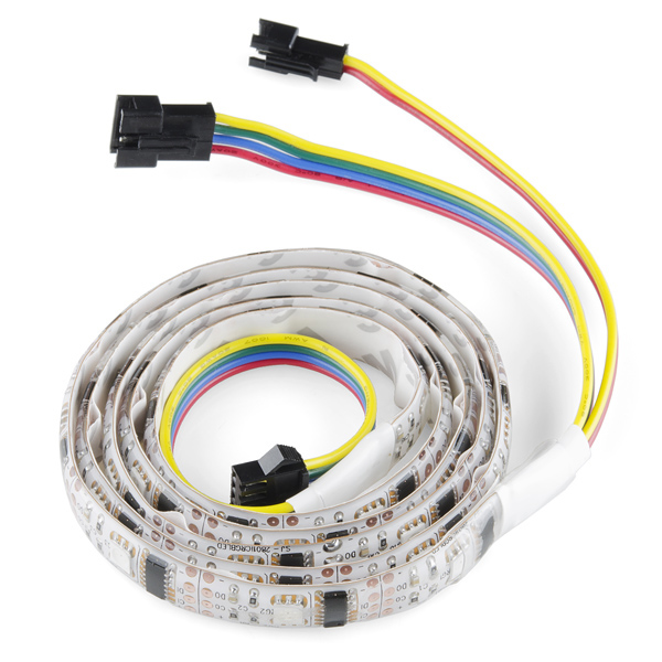
There is a recent change in the LED strips that we will be supplying with the EFeel_Basic unit. Originally we had plans to supply a one (1) meter long RGB addressable LED strip like these ones :https://www.sparkfun.com/products/retired/11272


These LED strips have been replaced with a newer model. We are currently looking into and testing the new models. So we will let everyone knows how that goes.


Tuesday, October 29, 2013

AGC (Auto Gain Controlled) Microphone


The idea of having an AGC mic came from us trying to think of ways people would use EFeel products. One of the questions we were faced with was “what if someone just wants to do something that looks awesome but doesn’t have the knowledge or time to create a sequence on Vixen?” From that we thought that our product should respond to the environment so the users don’t have to do anything and it would still look really cool.


AGC stands for “Auto Gain Controlled” which means it will adjust the volume of the mic without any user input needed. For example when using a camera to record in a club and playing back the footage the sound is horrible because it was so loud that mic was clipping. We also see this happens with those shirts that have a light up picture on them that respond to sound. When it’s too quiet it doesn’t work and when it is too loud it just stays on all the time. To make sure the microphone feature works in almost all environment it will adjust its gain (volume) based on the environment. This way the user can just show up to parties or any other events and the lights will respond to the surrounding sounds without any adjustment needed by the user.


So you may ask how is our progress on our cool AGC mic feature…
I can say it is on the next prototype that is going to be shipped out very soon. Other than that we are crossing our fingers.


Monday, October 28, 2013

Creating an EFeel outfit


Having bought tickets to a Halloween music festival I decided this would be a great time to test out our EFeel Pro model. So my friends Don Heer and Brandi Coker help me make some costumes out of EL wires that would be controled with our EFeel Pro. So here we go:

(get our EFeel here http://kck.st/1i93B51)


Costume 1:
This one is the first one that was made. The idea of was very simple and came from the logo I made. For our first prototype we had sewed all the EL wires on and that took a very long time so this time I tired hot gluing the EL wires to a shirt to see if it would work. Hot gluing turned out to be much faster and didn’t damage the EL wires, but it was a lot messier. The hot glue held pretty well and nothing came apart. Another issue was making sharp corners with EL wires for the circuit board trace design. So in-order to make the sharp corners I made a loop with the EL wires and covered the loop up with black electrical tape. The looping ended up not looking that great so next time I will probably loop the EL wires through the shirt or just bend the wires as tight as I can and use a lot of hot glue to keep there.


Costume 2:
This one was made by Don Heer and will be for Oregon State University. The costume is a white lab coat with about 50 feet of orange EL wires. The OSU part is done by hot gluing orange EL wires to a piece of cardboard and attaching the cardboard on the inside of the lab coat. the orange heart and glasses are done the same way, organe EL wire is glued on.


Costume 3:

This is Brandi Coker’s costume. It is also a lab coat and uses the same ideas as the orange lab coat design. EL wire is glued and ran through the lab coat to make the aperture logo on the back along with the heart, glasses, and turret figure in the front. There was a total of 30 feet of EL wires.


Friday, October 25, 2013

Making a Single Channel Driver

Before we jump into today's post, be warned: the picture quality is lacking! I only had the camera on my phone available and it's not a fancy phone... Anyway, onto the post!

I attempted to make a driver/inverter for a strand of EL Wire today. We've been talking about making one ourselves to attempt to make it smaller than what we have and be able to integrate it into our boards. So, this was just a test run to see if it's at all possible. I based it off of a schematic found in an article on Make:. The basics of what this circuit is supposed to do is that it takes a steady signal (always positive) and creates and alternating signal (switches between positive and negative) while increasing the voltage from input to output. It uses a timer to create the alternating signal (on/off) and then uses a step up transformer to create the higher voltage on the output. I had a limited amount and types of parts available for me to use, so I had to be a little creative. I took an old piece of protoboard to use and mapped out on my engineering paper where I wanted to lay out my parts and traces.
It's not the easiest to read, but you can kinda tell what I was thinking. From there I started soldering parts onto the protoboard and just going for it.
The picture shows that I started my board working from one side to the other. This is mainly because the parts that the whole thing is based around were on this side of the board. The blue box is a potentiometer which is used to control the frequency that the timer outputs. The black rectangle with the 8 silver legs is the timer. The black rectangle with the silver edge on the left is a transistor. The yellow ovals are capacitors and the light blue things are resistors. The reason for having multiples of the capacitors and resistors was because I didn't have the values for those that were on the schematic.A little improvising never hurts... Well, almost never!
From there, I continued putting in parts and creating "traces". The following picture is of the underside of the protoboard. This was my first time creating a full circuit on protoboard like this, and creating the traces was harder than I expected!
I had finished the board at this point and decided to try it out using a power supply and measuring the output with an oscilloscope. I got everything hooked up and to the settings I wanted. I then turn the power supply output on... and nothing happens. There is no output! Nothing is happening on the oscilloscope screen. I check all my connections and try again. Still, nothing!
One thing I did realize when checking over everything is that the transistor I was using was not quite what I needed. I knew that I wasn't using the same one listed in the schematic, but I thought it had the same qualities. The article mentioned something about a TIP120 Darlington transistor, but I didn't think much of it. I had never heard of a Darlington transistor before. So, when I was checking back over my finished work, I looked more into the Darlington transistor. I realize now that it's not the same as the TIP29 that I using. I'm not saying the transistor is the only reason why this didn't work. I'm sure there are other things that were not quite correct with my circuit.
So, no cool lights to show or pretty pictures to awe at. Just a circuit that doesn't work. This was a good learning experience for me. I learned about Darlington transistors, how to solder "traces" on protoboard, and that the correct parts would probably help in assembling a circuit.


Wednesday, October 23, 2013

First Production Run is in Full Swing


The final three boards to fulfill Utah Ballroom Dance's order have just made it in from our local PCB fab in Portland, Oregon. OSH Park has, once again, done a brilliant job. Plus we got a sticker! The order for the parts needed to populate the boards is in with DigiKey and we should be able to get these completed and ready for pick up by November. We're really looking forward to the production they put on with these and hope to get to at least one of their performances once the show is on (they're shows aren't only in Utah, btw).

Monday, October 21, 2013

T-shirt design

With the start of our Kickstarter we are all frantically working to get everything as close to perfect as we can so that we can deliver a polished product. Along with designing our lighting controllers we have designed some t-shirts as one of the perks for helping us out. Below is a render of the t-shirt design. It is a simplistic design that we hope people would like. Let us know what you think.


Wednesday, October 9, 2013

One LED Strip potential use

We're so close to going live with the Kickstarter! A few last minute items and we'll be able to set the Kickstarter site live. Stick with us and we'll let you know when!

One thing we want to show you are the potential uses for our boards. One thing we tested while doing early development is using individually addressable RGB LED strips. What that means is each LED on a strip can be a different color. There are many LED strips out there that only have all the LEDs one color at at a time, which can still be used with our boards, but we wanted to test the ease of use of the individually addressable LED strips.

The effects that can be created with individually addressable RGB LED strips is also very exciting. There are so many color choices available to play with and the patterns are a lot of fun. It was a good experience to play with the pretty colors to make something exciting! I will admit that once the strip had the color pattern desired, a lot of time was spent just looking at the lights change colors.

Driver and Transmitter Boards with RGB LED strip
The pattern the strip is showing, is the Red-Green-Blue Spectrum. It was designed to flow the colors through the strip. It looked like a rainbow shifting and wrapping around the ends. There are some video segments of it actually shifting through the colors in our Kickstarter video, so make sure to check that out once we go live to see the full effect!

So, this is one potential use for our project. You could have a light up belt, headband, table lighting, etc. using the LED strips. If you ever have any questions for us (about anything!) please leave a comment here on our blog or write on our Facebook page. We'd love to get some feedback and know what our supporters are interested in hearing from us!

Tuesday, October 1, 2013

Product Tiers

Our project has three different tier of boards we will be producing each targeted at different audiences. If someone just want to control some simple LEDs then there is no need to get our fully equip wireless unit so we took the time to create some smaller units to help meet everyone’s needs.


EFeel Basic
This unit is base unit capable of controlling a LED strip. It reads the pattern or sequence from an external micro SD card which can be programmed via Vixen. There will also be a microphone for audio control settings.

EFeel Plus
The Plus unit has everything the Basic unit has plus up to four channels of EL wire. This allows for control four EL wire channels at 10 ft per channel via an external micro SD card.

EFeel Pro
The Pro unit comes complete with control of two LED strips, eight channels of EL wire, and a transmitter for wireless controls.


Monday, September 30, 2013

Introduction

Hello, I am sure some of you might have heard we are starting a Kickstarter but are not sure what it is about. First, I would like to say thanks for all the support even though you have no clue what it is. =)

Lets just jump right into the details. We (Brian Benavidez, Chelsea Collette, and Tuan Truong) are creating a wireless lighting controller and we plan to push it to Kickstarter. Our project, Electric Feel, allows real-time wireless control of Electroluminescent (EL) Wire and LED Strips. Applications for our projects include wearable lights, art performances, and all forms of decoration. Our goal is to create a flexible and easy to use lighting controller. We have spent a lot of time creating something that is easy for the average consumer to use but has a lot of potential. We are excited to see what people can create with our project. We are currently in the process of getting everything together for our Kickstarter but we plan to keep updating everyone as we progress.


Thursday, September 26, 2013

Quiet Start

I know we started off loud and excited about Electric Feel and that it has been a bit quiet for the last few days, but we've been busy getting ready to launch! Most of what we're doing right now isn't the most exciting, but as we get going, it should look better and better. We hope you're as excited as we are to get this underway.

This week we worked on some filming for our video. Thankfully it was not a live, one and done shoot! The three of us are not the most natural in front of the camera. However, we had some laughs and got enough material to make an awesome, informative video. Following are just a couple pictures from our filming session.
 Tuan setting up one of the camera's we were using to film.
 Brian is taking down the white backdrop because we thought the brown one had a bit more life

Also this week, we are working on making our Kickstarter page look awesome and hopefully within the next couple days we can provide you a preview link to get a better look of what it's all about. We're still finishing our description and putting together the video, but it should be great!

We appreciate all of your support this early in the process! We hope that our support group keeps growing through our friends and friends of friends and everybody else that is willing to support what we're doing. Thank you!

Monday, September 23, 2013

Get Caught Up

So a lot of work has gone into this project this summer, here's the run down to this day:

Jesse from the Utah Ballroom Dance Company approached Oregon State University's Electrical Engineering Department to have some wirelessly controlled, light up dance suits. The interns at TekBots were given the task of researching and developing a system that can wirelessly control 6 suits with 8 channels of Electroluminescent Wire each.

We quickly distributed tasks to each of the interns (Tuan Truong, Chelsea Collette, and Brian Benavidez). The system logically broke down into three sections: the transmitter, the receiver, and the driver, the latter two being the devices physically attached to each dancer. Chelsea took on the driver, Brian took on the receiver, and Tuan took on the transmitter. Here is rev 0 of the boards:


The first boards worked for the most part but there was clearly a new revision in our future. The boards were larger than necessary (check out all that blank green space!) and would cost too much to produce them in quantity. The receiver needed a lot of additional work, extra hardware and unused microcontroller pinouts needed to go, and the power distribution needed to be addressed. This board could take in 12v which would be passed directly to the inverters needed to drive the wire at 100V, 2kHz, then regulate the 12v down to 3.3v to power the microcontroller. This was easy enough but we were wasting power dropping 12v to 3.3v using a linear voltage regulator. The solution here was to use a less power-hungry switching regulator to drop the 12v down to 5v, then use the linear regulator for the additional drop from 5v to 3.3v. The benefit here was that we could add a couple pinouts from the microcontroller to drive addressable LED strips like these:


Now we could offer Utah Dance the option of using LEDs in addition to EL wire. Awesome!

So we went to work on the second revision, adding some hefty power hardware and combining the receiver and driver into one, more compact board. The result:


Here is the board with all of the wires connected and ready to go (yeah, it's a lot). So we 3D printed a case and crimped on some JST connectors to try and clean everything up.
 Below is the final board inside the case which we were able to easily attach to a suit that Utah Dance put together for us.


That pretty much sums up the progress so far. Obviously there were many more small decisions made and hardware/software development which will come to light in future posts, but for the sake of length, we'll leave it at that for now.